You can do this, by selecting all sections you wish to display it on in the section manager (select multiple by CTRL>Left Click).
Then go to the Section Manager>Analytical Tools>Display 3D Model on Section
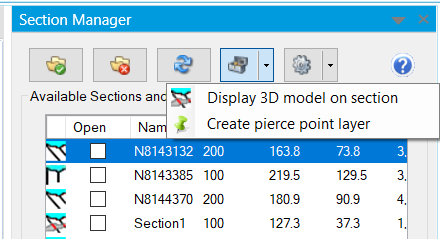
This allows the easy display of multiple .DXF and Discover 3D .FDB vector models onto the selected cross-sections as attributed polygons and polylines, each in their own TAB file layer. These input models can be polyhedron volumes (e.g. mineralisation isosurface halos or proposed open cut wireframes) or surfaces (such as fault planes or unconformity wireframes/TINS) modelled in either Discover 3D or a 3rd party application.
This allows the easy display of multiple .DXF and Discover 3D .FDB vector models onto the selected cross-sections as attributed polygons and polylines, each in their own TAB file layer. These input models can be polyhedron volumes (e.g. mineralisation isosurface halos or proposed open cut wireframes) or surfaces (such as fault planes or unconformity wireframes/TINS) modelled in either Discover 3D or a 3rd party application.
The tool will display the intesection of the vectors with with 2D section plane.
NOTE It will not project or include all data in the envelope, it will only show data that intersects the section plane. If you wish to see all data within a section envelope, you can do this dynamically with the Discover3D Cursor Plane.
For instance, this functionality allows you to take your 3D models, such as :
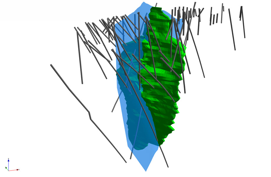
And slice / intersect them across multiple 2D sections, with an assigned style per model, producing polygons and polylines stored and managed on a per section basis:
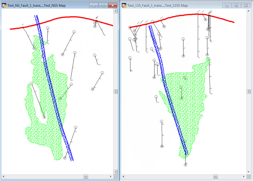
This capability therefore opens further analytical options within your 2D drillhole cross-sections, such as using the resulting sectional mineralisation polygons to constrain IDW grids interpolated from downhole assays within the sections.
For instance, this functionality allows you to take your 3D models, such as :
And slice / intersect them across multiple 2D sections, with an assigned style per model, producing polygons and polylines stored and managed on a per section basis:
This capability therefore opens further analytical options within your 2D drillhole cross-sections, such as using the resulting sectional mineralisation polygons to constrain IDW grids interpolated from downhole assays within the sections.


