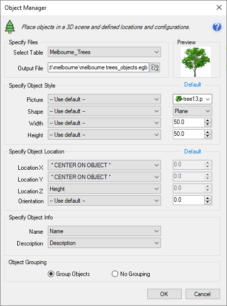
The Object Manager allows the 3D environment to be easily populated with multiple image objects.
Examples include displaying images of trees, vegetation, signposts, texturing walls and simple structures (e.g. buildings) and placing signboards on buildings.
The Object Manager can be used with both point and line objects.
This is a useful way of giving a 3D environment a sense of scale.

To add objects to the 3D environment:
1. Open the Discover 3D>Utilities>Object Manager tool.
2. Select a Table containing the objects to populate the 3D window.
3. Define an Output File name and location.
4. Adjust the following settings:
Picture
If ‘-- Use default --’ is selected define an image to use from the adjacent dropdown.
If a field is selected for each object an alternative image can be used by either defining the full path to an image file in that field, or by defining the image file name in the field if the image is located in the same folder as the table being used.
Shape
If ‘-- Use default --’ is selected, define the shape of the displayed image from the adjacent dropdown.
Select from Plane (a single image presented as a vertical plane), Cross (two perpendicular images crossing centrally, creating an illusion of a 3D image object from a distance) or Box (four images placed in a square around the object).
If a field is selected for each object, and contains one of these values plane, cross or box, this will determine the shape of each individual object.
Width
If ‘-- Use default --’ is selected, define the width with a value entered into the adjacent box.
If *LINE SEGMENT WIDTH* is selected, the length of the line segment will determine the object width.
If a field is selected, for each object the value entered will determine the object width.
Height
If ‘-- Use default --’ is selected, define the height with a value entered into the adjacent box.
If a field is selected, for each object the value entered will determine the object height.
Location X
Select a method to set the X coordinate location.
If * CENTER ON OBJECT * is selected, when a point object is used, the X coordinate of that object will be the location used.
If * CENTER ON LINE SEGMENTS * is selected, when a line object is used, the centre point X coordinate of the line will be the located used.
If ‘-- Use default --’ is selected, you can define an X coordinate as the location (using this method all object coordinates will be the same).
If a field is selected, for each object the value entered will determine the object X coordinate location.
Location Y
Select a method to set the Y coordinate location.
If * CENTER ON OBJECT * is selected, when a point object is used, the Y coordinate of that object will be the location used.
If * CENTER ON LINE SEGMENTS * is selected, when a line object is used, the centre point Y coordinate of the line will be the located used.
If ‘-- Use default --’ is selected, you can define an Y coordinate as the location (using this method all object coordinates will be the same).
If a field is selected, for each object the value entered will determine the object Y coordinate location.
Location Z
If ‘-- Use default --’ is selected, define the Z location with a value entered into the adjacent box.
If a field is selected, for each object the Z value entered will determine the object Z.
Note
If the image objects are to be located on a surface (e.g. a DEM or topographic surface), set ‘-- Use default --’ to 0.
Once the images are displayed in the 3D window, use the Offset tab of the Images Properties dialog to add a DTM offset using the appropriate surface.
Orientation
If * LINE SEGEMENT ANGLES * is selected, when a line object is used, the bearing of that line will determine the image object orientation.
If ‘-- Use default --’ is selected, define the orientation with a value entered into the adjacent box.
If a field is selected, for each object the value entered will determine the object orientation.
Name
If ‘-- Use unique number --’ is selected, each object will be assigned a unique number.
If a field is selected, for each object the value entered will define the object name.
Description
If ‘-- None --’ is selected, each object will not be assigned a description.
If a field is selected, for each object the value entered will define the object description.
Object Grouping
Two options are available:
Group Objects – This will assign all objects into one group when displayed in Discover 3D, individual objects can still be filtered in 3D.
No Grouping – This will display all individual objects in a separate branch in Discover 3D, it will create a large list of objects in the Session Window.
5. Click OK to create the 3D objects.


