Occurrence
I need to view both my local mine grid data and real earth data in the one mapper window. Traditionally many people use a simple Non-Earth (metres) coordinate system to display local mine gridded data, or data from a sampling grid in a project area.
Creating a custom affine projection will allow the local mine data to be directly compatible with any real world coordinate system.
Solution
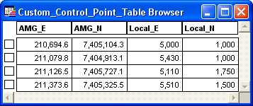
The control point table for a custom affine projection transformation must contain four columns which read from left to right as UTM_Easting, UTM_Northing, Local_Easting and Local_Northing. The naming convention
of the column headings is not important, but the order of the columns is critical. An example of a control point table can be seen below.
To generate a custom projection system for the non-earth coordinates -
1. Open the table to transform into MapInfo. The transformation target table must be mappable and in a standard projection, e.g. UTM or MGA. If no data is available, you may also use the Control Point table for the transformation target table, by simply Creating Points for the UTM (MGA) coordinates.
2. In the DISCOVER>Projections>Custom Transform (or Discover>Data Utilities>Transform Coordinates) dialog, select the table to transform from the Transformation Target Table list.
3. Choose Affine from the Transformation Type pull-down list.
4. Click on the Control Point Table button and browse to the control point table. The selected control point table will be displayed on the Control Point Button. This table does not need to be mappable, although if it is, it should in the base projection (.ie. UTM or GDA).
5. Check the Make Affine Coordsys box
6. Click OK.
7. Select the required standard projection for the UTM (MGA) coordinate fields from the Choose Projection dialog (this will be the base projection for which the custom affine is based on).
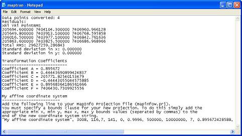
8. Discover will create the affine transformation and add the custom coordinate system description to the MAPTRAN.LOG file. An example Maptran.log can be seen below.
8. Copy the line beginning “My affine coordinate system” from the MAPTRAN.LOG file
and paste into the bottom of your MAPINFOW.PRJ file. The MAPINFOW.PRJ file is located in the
..\\MapInfo\Professional directory.
9. Assign a new name for the custom projection and add a new projection Category line above if desired.
This projection category can be used to keep all your custom projections together, and should be in the
format below:
"--- Custom Projections ---"
10. This will then use the default bounds to achieve sub-decimeter accuracy. Alternatively to achieve higher precision, change the "100x" to "300x" and add appropriate bounds clause to the projection line. To specify bounds for the new projection enter the appropriate min_x, min_y, max_x, max_y values for your data as per the example below.
Example of a custom projection's in the MAPINFOW.PRJ file:
"--- Custom Coordinate Systems ---"
"Sylvania Local Grid", 1008, 13,7, 141, 0, 0.9996, 500000, 10000000, 7, 0.895898, -0.444543, 3108129.02, 0.444537, 0.895887, -6726798.31
"Sylvania Local Grid (bounds)", 3008, 13,7, 141, 0, 0.9996, 500000, 10000000, 7, 0.895898, -0.444543, 3108129.02, 0.444537, 0.895887, -6726798.31, -500000, -500000, 10000000, 10000000
11. For any existing maps in local non-earth, you will need to recreate the points in the new custom projection.
For any existing maps in UTM (MGA), you can convert these into the local grid by simply re-projecting and selecting the custom projection.
Note you cannot reproject to/from non-earth to any other projection (UTM or Affine).
12. You ought to also add the projection to your Encom.prj, to use in Discover's reprojection tools - see the related article for more details.


